
Table of Contents
- Step 1: Gather Air Conditioner Nameplate Ratings
- Step 2: Perform the Air Conditioner Amps Calculation
- Step 3: HVAC Circuit Sizing and Protection
- Step 4: Electrical Load Calculation for Multiple Air Conditioners
- Step 5: Confirm the Whole-of-Home or Whole-of-Site Load
- Common Mistakes That Throw HVAC Electrical Load Calculations Off
- When to Call a Licensed Electrician
- Frequently Asked Questions
Last Updated: October 8, 2026
Step 1: Gather Air Conditioner Nameplate Ratings
Calculating HVAC electrical load requirements starts with one small metal plate.
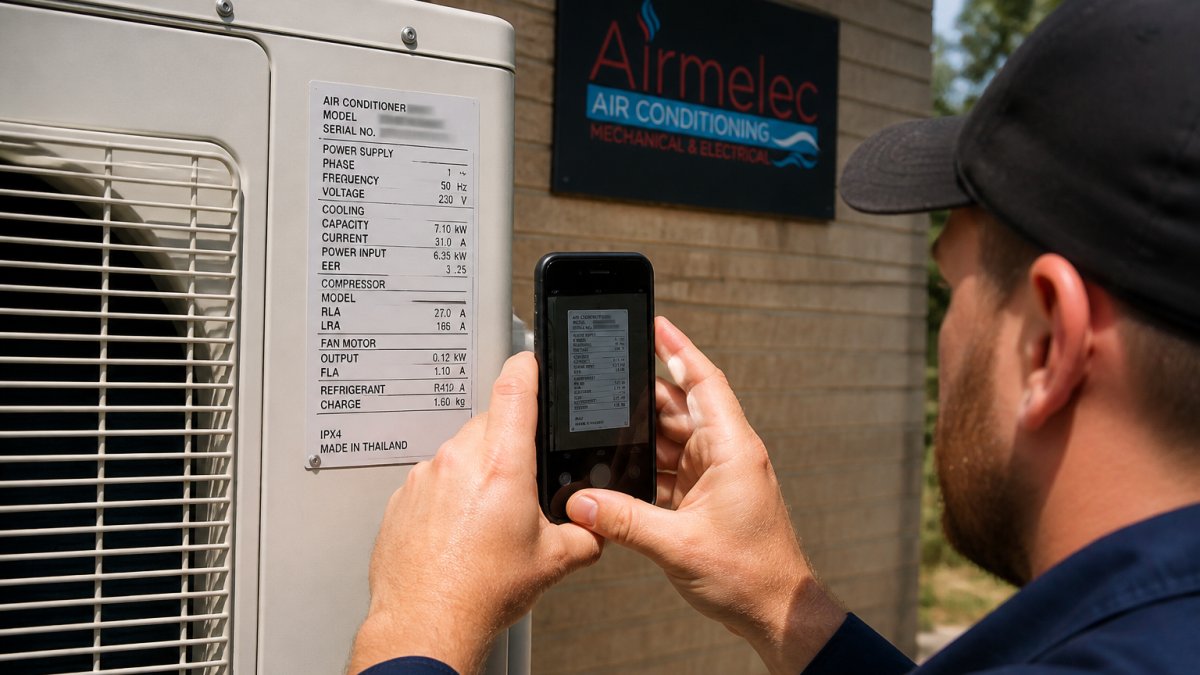
Air Conditioning & Electrical handles this work daily across the Hawkesbury and Hills region, and the same rule applies everywhere: read the plate before you size anything.
HVAC electrical load is the total current and power a heating or cooling system draws when running, used to size circuits, protection and supply capacity.
Where to Find the Nameplate and What to Record
The nameplate sits on the outdoor condenser unit, usually on the side or back panel. On split systems, check the indoor unit too.
Record these details:
- Model and serial number
- Voltage and phase
- Rated running current in amps
Photograph the plate. Faded print is a common trap, and a photo saves a second trip outside.
If the plate is sun-bleached or painted over, check the manufacturer’s installation manual by model number. It lists the same electrical data and often adds starting current figures the plate leaves off.
Step 2: Perform the Air Conditioner Amps Calculation
The air conditioner amps calculation is simple once you have the plate. Amps equal watts divided by volts for resistive loads, but motors behave differently, so trust the nameplate figure.
Here is the working method:
- Note the rated running current from the plate.
- Add the outdoor fan and indoor fan currents if listed separately.
- Apply the manufacturer’s minimum circuit ampacity as your design figure.
- Check the maximum breaker size the unit allows.
Why the Nameplate Amps Beat a Watts Conversion
Converting watts to amps looks tidy on paper but fails in practice. Air conditioners use induction motors whose compressors draw a surge at start-up; a watts conversion ignores power factor and starting current, so it understates real demand. The plate already accounts for these factors. A common mistake is sizing a circuit from a brochure’s “power input” figure, that describes energy use, not circuit demand.
Step 3: HVAC Circuit Sizing and Protection
HVAC circuit sizing means matching cable, breaker and isolation to the unit’s nameplate demand, not the nearest guess. Get it wrong and nuisance tripping or fire risk follows.
Work through the requirements in order:
- Cable sized to the minimum circuit ampacity
- Breaker no larger than the maximum size stated on the plate
- Correct cable type for the route, including UV-rated cable outdoors
Every circuit needs overload and short-circuit protection: the breaker protects the cable, and the unit’s internal protection handles the compressor.
The HVAC-Specific Compliance Checklist Most Guides Skip
General electrical safety content describes hazards; a practical HVAC checklist describes what to verify on the actual installation. Work through these in order and record each result:
- Supply and circuit identification, confirm the circuit is dedicated to the HVAC equipment and labelled at the switchboard.
- Conductor sizing, check the active, neutral and earth conductors against the minimum circuit ampacity on the nameplate, accounting for route length and derating.
- Overcurrent protection, verify the breaker or fuse does not exceed the maximum size stated on the plate, and that it is the correct type for the circuit.
- Disconnect and isolation, confirm a means of isolation is fitted within sight of the outdoor unit and is clearly identified.
- Earthing and bonding, check the protective earth is continuous and terminated correctly at the unit and the switchboard.
- RCD protection, confirm residual current protection is fitted where the applicable wiring rules require it for the circuit type and location.
- Cable support and protection, check the cable is supported, protected from mechanical damage, and rated for the environment (UV, heat, moisture).
- Terminations, verify all connections are tight, correctly rated, and free of exposed conductor.
- Manufacturer instructions, confirm the installation follows the manufacturer’s wiring diagram and any specific protection requirements.
- Commissioning records, record the tests performed and the results before handover.
Photograph each checklist item as you complete it. A dated photo set turns a verbal assurance into evidence you can produce at inspection, sale or warranty claim.
Conductor Sizing, Overcurrent Protection and Bonding in Practice
Conductor sizing for HVAC equipment is not simply matching the breaker to the cable. The nameplate’s minimum circuit ampacity sets the cable floor, and the maximum breaker size sets the protection ceiling; the cable must be rated for the current it carries after derating for ambient temperature, grouping or installation method. Overcurrent protection must sit between those figures, a breaker larger than the plate maximum may not protect the equipment’s internal wiring, while one smaller than the minimum circuit ampacity may trip under normal starting current.
Fitting a larger breaker to stop nuisance tripping is dangerous. The breaker no longer protects the cable, and the cable can overheat inside a wall before the breaker ever trips. The same applies to bypassing or removing an isolator because it is inconvenient.
Jurisdiction and Code-Version Differences
HVAC electrical requirements are set by the wiring rules and standards adopted in each jurisdiction, and the version in force changes over time. A method compliant under an earlier edition may not satisfy the current one, and local authorities may add their own requirements for isolation, RCD protection or documentation. Before relying on any figure or method, confirm which edition applies and check whether the local regulator or supply authority has extra requirements.
Documentation and Handover
At the end of the job, paperwork matters as much as the wiring. Keep these with the installation records:
- The electrical certificate or compliance documentation required in your jurisdiction
- Test results for insulation resistance, continuity and polarity
- The commissioning record showing the checks performed and the results
- The manufacturer’s installation manual and wiring diagram
These records support warranty claims, safety inspections and property transactions. Missing paperwork is a common reason a compliant installation becomes a problem at sale or lease.
Step 4: Electrical Load Calculation for Multiple Air Conditioners
The electrical load calculation for multiple air conditioners adds one more question: will they all run at once? In most homes, no. Add the full demand of each unit first, then apply diversity, which recognises that not every appliance draws peak current at the same moment. A whole-of-home assessment uses this logic, which is why a house with four split systems does not need a supply sized for four units running flat out.
Applying Diversity to the Total Demand
Diversity factors vary by installation type and local rules. A ducted system with one compressor behaves differently from four separate splits on one switchboard.
| Scenario | Approach | Watch For |
|---|---|---|
| Single split system | Full nameplate demand | Starting current |
| Two to three splits | Full demand, then apply diversity | Shared circuit risk |
| Ducted system | Nameplate plus indoor fan | Zoning controls |
| Mixed HVAC and appliances | Whole-of-site assessment | Supply capacity |
Never guess a diversity figure. The applicable standard sets the method, and the version in force changes between areas.
A Step-by-Step Method You Can Actually Follow
A practical multiple-unit calculation follows a repeatable sequence. Work through it in order, recording each figure:
- List every unit, model, rated running current, minimum circuit ampacity and maximum breaker size from each nameplate.
- Add the full demand, sum the rated running currents and the minimum circuit ampacities for all units.
- Identify the largest starting current, for non-inverter units, note the surge the compressor draws at start-up.
- Apply the diversity method, use the method set by the applicable standard for the installation type, not a rule of thumb.
- Add non-HVAC loads, include other large appliances and circuits that may run at the same time.
- Compare to supply capacity, check the total against the switchboard and supply maximum demand.
- Document the result, record the figures, the method used and the outcome for the installation records.
This turns a vague “apply diversity” instruction into a repeatable calculation you can check and hand over.
Commissioning Tests and Measurable Acceptance Criteria
Once installed, commissioning confirms the calculation was correct and the installation is safe. Specific tests and thresholds vary by equipment and wiring rules, so use the manufacturer’s instructions and the relevant standard rather than a universal figure.
Checks commonly performed at commissioning include:
- Insulation resistance, measured and recorded against the value required for the circuit type.
- Continuity and polarity, confirmed at each outlet and at the unit.
- Earth continuity, verified from the unit back to the switchboard.
- RCD operation, tested where RCD protection is fitted, with the trip time recorded.
Record each result with the date, instrument and tester. A commissioning record with measured values beats a tick-box sheet because it shows what was actually verified.
A multiple-unit calculation is only as good as its records. List every unit, apply the correct diversity method, compare to supply capacity, and commission with measured results you can hand over.
Documentation for Multiple-Unit Installations
Multiple-unit installations generate more paperwork, not less. Keep the nameplate data for every unit, the diversity calculation and method, the switchboard schedule, the commissioning results, and the compliance documentation required in your jurisdiction. If a unit is replaced later, the records show what the original calculation assumed and whether the replacement changes the demand.
Step 5: Confirm the Whole-of-Home or Whole-of-Site Load
The final step checks whether the supply can carry the new total. This is the point where many DIY calculations fall apart.
A switchboard has a maximum demand figure, and adding air conditioning pushes it up. If the total exceeds what the board and supply can handle, an upgrade is needed before installation, a larger main switch, a new circuit, or in older homes a full board replacement.
Common Mistakes That Throw HVAC Electrical Load Calculations Off
Errors here are predictable, and most come from skipping the plate.
The usual culprits:
- Using watts instead of nameplate amps
- Ignoring starting current on non-inverter units
- Forgetting the indoor fan load
- Sizing from the old unit when replacing
Each one leads to the same outcome: a circuit that trips, a cable that runs hot, or a system that never performs as promised.
There is also the documentation gap. Certificates of compliance and inspection records matter, especially at ownership change. Missing paperwork creates problems at sale time.
The nameplate is the single source of truth. Every reliable HVAC electrical load calculation traces back to it, and every shortcut around it leads to a defect.
When to Call a Licensed Electrician
Some jobs sit firmly in licensed territory, and air conditioning circuits are among them.
Call a licensed electrician when:
- A new circuit is needed from the switchboard
- The board needs an upgrade or new protection
- Cable routes pass through walls, ceilings or underground
- Any doubt exists about the existing wiring
At Air Conditioning & Electrical, our fully licensed technicians handle both the HVAC and electrical sides of an installation.
We are also an approved installer under the NSW Government’s Home Energy Saver loan program, with 0% interest finance options available through Brighte for eligible energy-efficient upgrades.
Frequently Asked Questions
How do you calculate the electrical load of an HVAC system?
Start with the nameplate on the outdoor unit. Record the rated voltage, the rated load amps or full load amps, and the minimum circuit ampacity. Multiply the circuit ampacity by the supply voltage to estimate the load in volt-amps, then add any indoor air handler or supplementary electric heater. For a whole-of-home answer, add that figure to the rest of the household demand rather than treating the HVAC system in isolation.
How many amps does an air conditioner need?
It depends entirely on the unit. A small split system might draw a handful of amps, while a large ducted system with electric backup can draw considerably more. The only reliable figure is the rated load amps printed on the nameplate, not a rule of thumb based on kilowatts. Always size the circuit from the nameplate rating, and remember that the starting current on compressor startup is higher than the running current.
Does an air conditioner need a dedicated circuit?
Fixed air conditioning equipment is generally required to have its own dedicated circuit, protected by the correct circuit breaker and residual current device where the wiring rules require it. Sharing a circuit with general power outlets risks nuisance tripping and overloaded circuits. If you are adding a new system to an older switchboard, have a licensed electrician confirm there is spare capacity before the unit is installed.
When should an electrician check an HVAC electrical load calculation?
Before any new installation, before adding a second or third system, and whenever a switchboard keeps tripping. An electrician should also review the calculation when you add a granny flat, extend the home, or install a solar and battery system, because those changes alter the total demand. Get the check done at the design stage so circuit protection and cable sizing are right the first time.